Seismic imaging historically makes many assumptions, one of which is that the earth is isotropic and acoustic wavefields travel with equal speed in all directions. This assumption breaks down in many geological scenarios, leading to poorly-focused seismic images and mis-positioned seismic events. The discussion below serves as a general tutorial on the way that PGS can incorporate increasingly sophisticated descriptions of anisotropy into the way that seismic images are created. The accurate description of azimuthal parameters during anisotropic velocity model building require the availability of suitable azimuthal information in the recorded data. As a minimum, this implies the availability of overlapping datasets with orthogonal shooting directions, and ideally, the availability of full-azimuth (FAZ) data acquired with two or more vessels operating simultaneously.
Anisotropic Imaging
- VTI velocity model building enables correct seismic processing and imaging when most anisotropic effects can be attributed to the layering of flat geological layers.
- TTI velocity model building is appropriate when most anisotropic effects can be attributed to the tilted layering of geological layers where the tilting is aligned with the acquisition direction.
- ORT velocity model building corrects for anisotropic effects attributed to the tilted layering of geological layers where the tilting is aligned with the acquisition direction, and vertical fracturing is present wherein the fracture orientation is either parallel to or at 90° to the acquisition direction.
- T-ORT velocity model building enables correct seismic processing and imaging when most anisotropic effects can be attributed to the tilted layering of geological layers where the tilting is aligned with the acquisition direction, and vertical fracturing is present wherein the fracture orientation is at an arbitrary direction to the acquisition direction.
Basic Theory
It was always recognized that the subsurface of interest to seismic exploration is layered, and this layering imposes an anisotropic fabric onto the rocks whereby pressure waves travel somewhat faster along the layers in comparison to their speed across layer boundaries. Almost thirty years ago, Leon Thomsen, then working with Amaco, recognized that most anisotropy in rocks is weak rather than behaving in strictly textbook fashion, and therefore he was able to provide simple mathematical approximations defined by the dimensionless Thomsen parameters epsilon (ε), gamma (g) and delta (d), which together with a knowledge of the compressional wave and shear wave velocities made anisotropy tractable for seismic processing and imaging. For acoustic media where no shear wave propagation is acknowledged, the most common assumption for towed streamer seismic, epsilon (ε) quantifies the velocity difference for wave propagation along and perpendicular to the symmetry axis, delta (d) controls the P-wave propagation for angles near the symmetry axis, and essentially captures the relationship between the velocity required to flatten gathers (the NMO velocity) and the zero-offset average velocity as recorded by check shots, and as we are not concerned with shear wave propagation gamma (g) can be ignored (set to zero). It follows that d is the key parameter required to convert seismic velocities optimal for seismic imaging to velocities optimal to correctly predict the depth of interest for exploration drilling. d is independent of horizontal velocity, and can be either positive or negative.
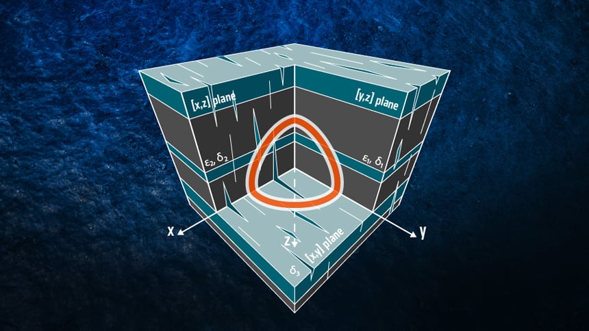
In addition to being layered, the earth has structure—the layers are tilted, so Tilted Transverse Isotropy (TTI) velocity model building requires the explicit knowledge of epsilon (ε) and delta (d), in addition to the bedding plane dip with respect to the inline and cross-line grid axes of the 3D survey being processed. Furthermore, the earth tends to have an azimuthal component of an isotropy too, typically associated with oriented stresses of fracturing (see figure below). This scenario, referred to as orthorhombic anisotropy, can also be extended to tilted orthorhombic anisotropy which also acknowledges the structural dip of the affected layers.
 An orthorhombic model produced by parallel vertical cracks embedded in a medium composed of thin horizontal layers; a scenario associated with orthorhombic or tilted orthorhombic anisotropy.
Anisotropic Processing and Imaging in Practice
Twenty years ago the seismic industry recognized that simple anisotropic modifications to the basic theory used for building subsurface models were necessary as seismic acquisition became capable of towing streamer longer than a few kilometers, and the long offset normal moveout of seismic gathers (the curvature of seismic events at large distances between the source and receivers along each streamer) could not be corrected using simple geometric assumptions. A generalized description of how epsilon (ε) and delta (d) affect long offset moveout known as VTI (vertically transverse isotropy) was introduced. VTI velocity model building acknowledges that vertically-layered thin geological formations introduce the moveout behavior of seismic gathers, but assumes that all the geological layers are flat, contain no vertical fracturing, and that seismic wavefields travel horizontally with equal speed in all azimuthal directions within each layer.
Several years later, the next evolution in anisotropic seismic processing was the extension of VTI theory to also acknowledge dipping geological strata. TTI (tilted transverse isotropy) velocity model building still assumes that each geological layer contains no vertical fracturing, and that seismic wavefields travel horizontally with equal speed in all azimuthal directions within each (tilted) layer.
The latest evolution in anisotropic velocity model building has been that fracturing influenced by regional stress regimes can cause the seismic wavefields to travel with different speeds in different azimuthal directions within each layer. One effect upon seismic processing and imaging is that a given anisotropic subsurface velocity model may perfectly focus and structurally position the seismic events for a 3D survey acquired in one direction, but the same anisotropic subsurface velocity model may be completely inappropriate for a survey acquired in the same location at 90° to the other survey, resulting in the seismic events being mis-focused (poor resolution) and/or mis-positioned (drilling targets occur in the wrong depth and and/or at the wrong location). In the worst case, the geological structures on incorrectly produced seismic images may be completely misrepresentative of the actual geology.
ORT (orthorhombic) anisotropic velocity model building acknowledges that unique epsilon (ε) and delta (d) parameters must be derived for each geological layer, based on a three-dimensional coordinate system, and assuming that the fractures are either parallel or orthogonal to the direction of geological tilt. Note in the illustrations above that ORT velocity model building also requires a knowledge of the fracture azimuth, bedding tilt and bedding rotation not necessarily aligned with the survey acquisition direction (i.e. the X and Y directions are arbitrary). Unfortunately, conventional narrow-azimuth (NAZ) surveys acquired with one vessel towing streamers, lack the azimuthal information that will robustly enable the estimation of ORT velocity model parameters. At least two overlapping orthogonal NAZ surveys (90° difference in acquisition direction) are required to pursue robust ORT velocity model building, and there will in fact preferably be three overlapping surveys with different shooting directions. Most commonly, two NAZ surveys may be available, probably acquired with somewhat different acquisition configurations, and with differences in acquisition direction somewhere between 45 and 90°. Assumptions will initially be made that each survey azimuth can be described using TTI anisotropy, and the estimation of ORT model parameters will attempt to derive the seven parameters necessary to describe the anisotropic effects observed on all relevant 3D datasets.
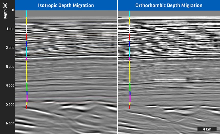
In the ultimate scenario, T-ORT (tilted orthorhombic) anisotropic velocity model building allows the fracture direction to be independent of the direction of geological tilt. The figure below illustrates the improvements in seismic imaging in a survey location where ORT velocity model building was necessary to optimally combine different overlapping 3D datasets acquired in different directions.
 Comparison of isotropic seismic processing and imaging (left) versus orthorhombic anisotropic seismic processing and imaging (right). Note the different event-to-well tie on the right (correct structural positioning) and the improved seismic event focusing on the right (higher resolution).
Again it cannot be underestimated how the complexity of the anisotropic model is bounded by our ability to accurately estimate parameters using surface seismic and/or well data. Any additional azimuthal information may be critical to the accuracy of anisotropic velocity model estimation.
Summary
All the PGS velocity model building solutions and all the high-end PGS seismic imaging solutions have VTI, TTI and ORT anisotropic capability, as do the conventional Kirchhoff time and depth migration solutions. The adoption of ORT (orthorhombic) velocity model building explicitly depends upon the availability of rich azimuth information for a wide range of offsets throughout the survey area. In practice, this means that at least three survey acquisition directions are available, although two may suffice in some cases. This requirement lends itself to multi-azimuth (MAZ) acquisition wherein an additional one or two survey acquisition directions are acquired in addition to an existing survey azimuth. Alternatively, one full-azimuth (FAZ) survey should satisfy all the requirements for optimal target illumination, coherent noise attenuation, and orthorhombic velocity model estimation.